Free
Counter Code 
| Welcome
to Amateur Radio AI2Q in
Kennebunk, Maine, USA Updated: 10 July 2024 Copyright@ 2022, Alex Mendelsohn, All rights reserved.
Send
comments to ai2q (at)
ai2q.org ==================================================================================== The native American name Kennebunk means "long cut bank," a name that's a reference to the mouth of the Mousam River. Hundreds of years ago, it
was a landmark to Indians the coast.
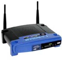
******************************************************* Click here to access Alectronix radio and electronics repair services. ******************************************************* NEW: An Old Buzzard’s Guide to Getting Started With HSMM-Mesh™ (also known as Broadband Hamnet™ ) Click here to access the latest version (v1.06) of the illustrated Microsoft Word file (338 kbytes) describing how to flash Linksys routers, or right click on the blue text link above and choose Save. Alternatively, you can access the content from the N5DUX Web site (earlier version). Here's a list of suitable Linksys routers:
==================================================== NEW:
Mesh novice? Want
to know more? Click here to view an introductory Broadband Hamnet slide show. ******************************************************* Read about the Albacore submarine radio room restoration. (updated 4-Nov. 2014). Click here to access presentation files used in the New England Radio Discussion Society's electronics course.The original PowerPoint files have been converted to .PDF format files courtesy N1QX. Click here to view my version of the G3XJP-designed PIC-a-STAR Software Transmitter And Receiver using home-etched and drilled double-sided circuit boards (built 2007). The second PIC-a-STAR HF transceiver at AI2Q is built on blank Chinese circuit boards sourced by VK3PE (built 2013). Click here to learn about my 600-watt MOSFET amplifier for the PIC-a-STAR. Learn more about the "Softrock" Software Defined Radio project at AI2Q here. Click here for notes about my 2-wire Beverage receiving antenna. Click here to jump to a 455-kHz product detector hitched to a MIL-surplus R-390A receiver. Click here to learn about the famous K8IQY-designed Model 2N2/40 all-2N2222 40-meter CW QRP rig, as built by AI2Q. Click here for some details of the Teletype RTTY system at AI2Q. Click here to check out a 1930s-style 8-watt 6L6 transmitter and matching 2-tube regenerative receiver. The chief op at AI2Q doesn't live by QRP alone. Click here to view the fire bottle rigs. Want to see a messy, but functional, 20-meter homebrew SSB/CW rig? Click here. Click here to view KA9Q TCP/IP software files. On this page you'll also find links to the notes for the Keep It Simply Sideband (KISS) beginner's SSB transceiver. Scroll to the bottom of this page for KISS construction info buttons.
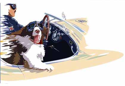
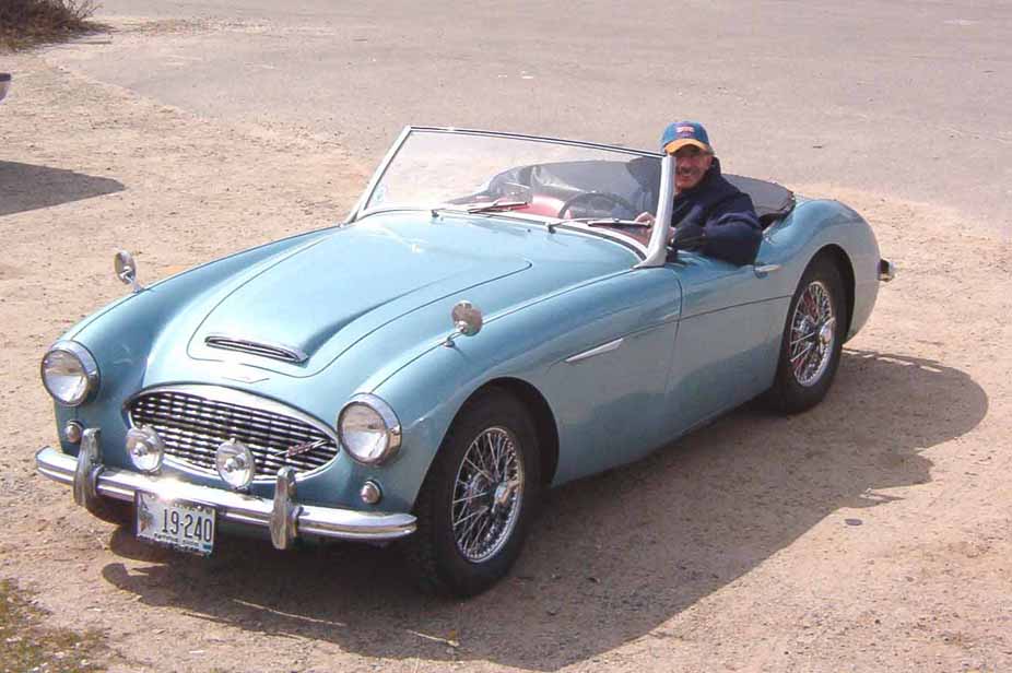
================================================================== Check out the "Blue Mainie," a 1960 Mk.I Austin-Healey 3000 named by N2RI, Paul. Click here for a photo of the chief op at the wheel. Click here to see my right-hand drive 1946 MG TC. It was among the first 1000 such vehicles built immediately after WW-II, and is original in most respects. The MG Car Company in Abingdon started exporting to the United States in 1948. And, remember:
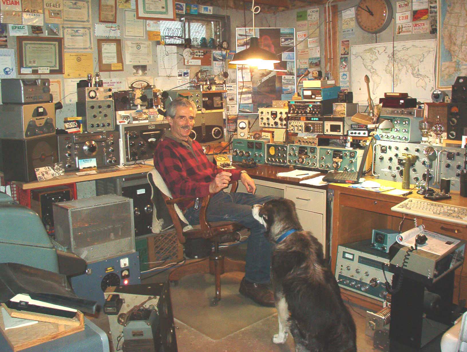
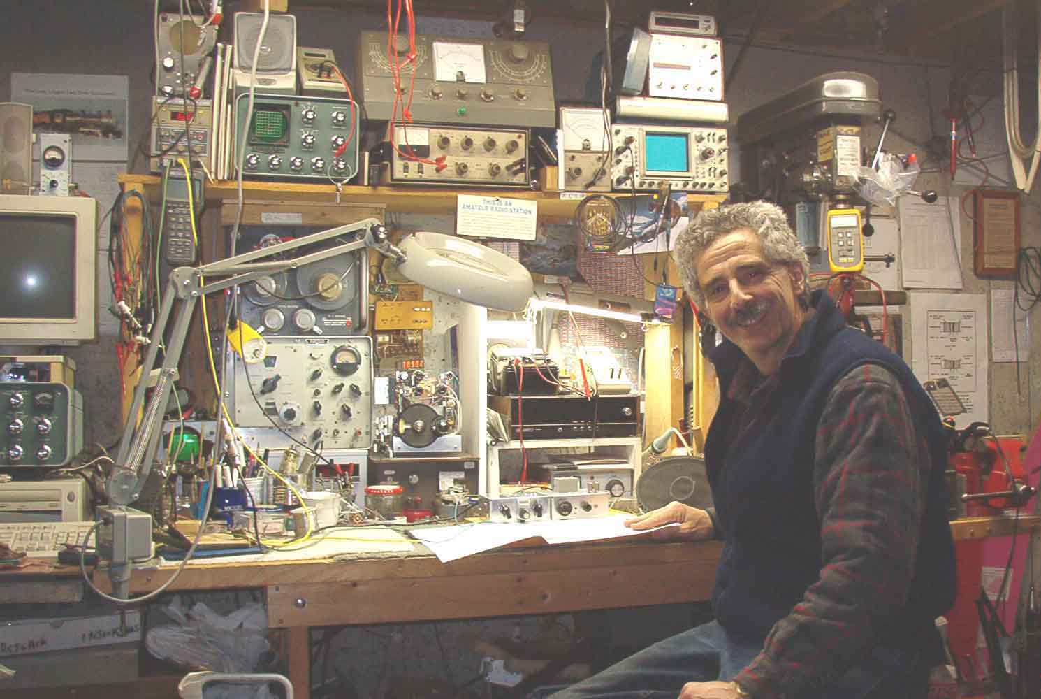
Here's "chief op" Alex with "second op" Smokey (now, sadly, a Silent Key) at the main operating position (May 2006). The main rig is a Ten-Tec Omni-V. It can drive one of three homebrew tube-type amplifiers or a Heathkit SB-220. The homebrew PIC-a-STAR (aka STAR) also covers 160M through 10M, SSB and CW. It drives a homebrew push-pull-parallel 4-MOSFET solid-state 600W amplifier. The Model 28 Teletype Corp. teleprinter is just visible on the left. A Heathkit Apache (for AM) resides on a dolly under the operating desk to the right. An Atlas 210-X is occasionally used mobile, and a Ten-Tec Argonaut 515 runs QRP. Receivers include a Collins 75A-4 (a gift from the estate of K7AK), a Collins 51J-4 with Hammarlund HC-10 SSB detector, a National HRO-60 (used with the Apache), a 1934 National HRO, a Stewart-Warner R-392, a Collins R-390, and a Motorola R-390A. Also visible is a 1957 Collins KWM-1 (arguably the world's first transceiver) and a Drake TR7-A. Boatanchors include a Heathkit AR-3 (my first receiver in 1959), a National NC-57, a National SW-54, Heathkit SB-303/SB-401 twins, a Hammarlund HQ-120-X, a Hallicrafters SX-99 (my 1959 Novice receiver), a Heath DX-35, and a Hammarlund HQ-180. The antenna farm consists of a center-fed doublet that's about 150-ft. long and at a ehight of about 70-ft. The feedline is homebrew open-wire line. The station also includes a pair of phased 1/4-wave verticals fed through a homebrew quadrature phase-shift network. Switched by relays, the pattern can be directed east or west. It operates in the 75M "DX window." The station also includes a 2-wire Beverage for receiving. The KISS Transceiver
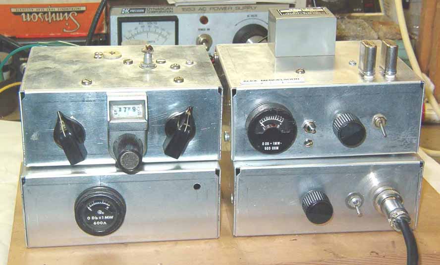
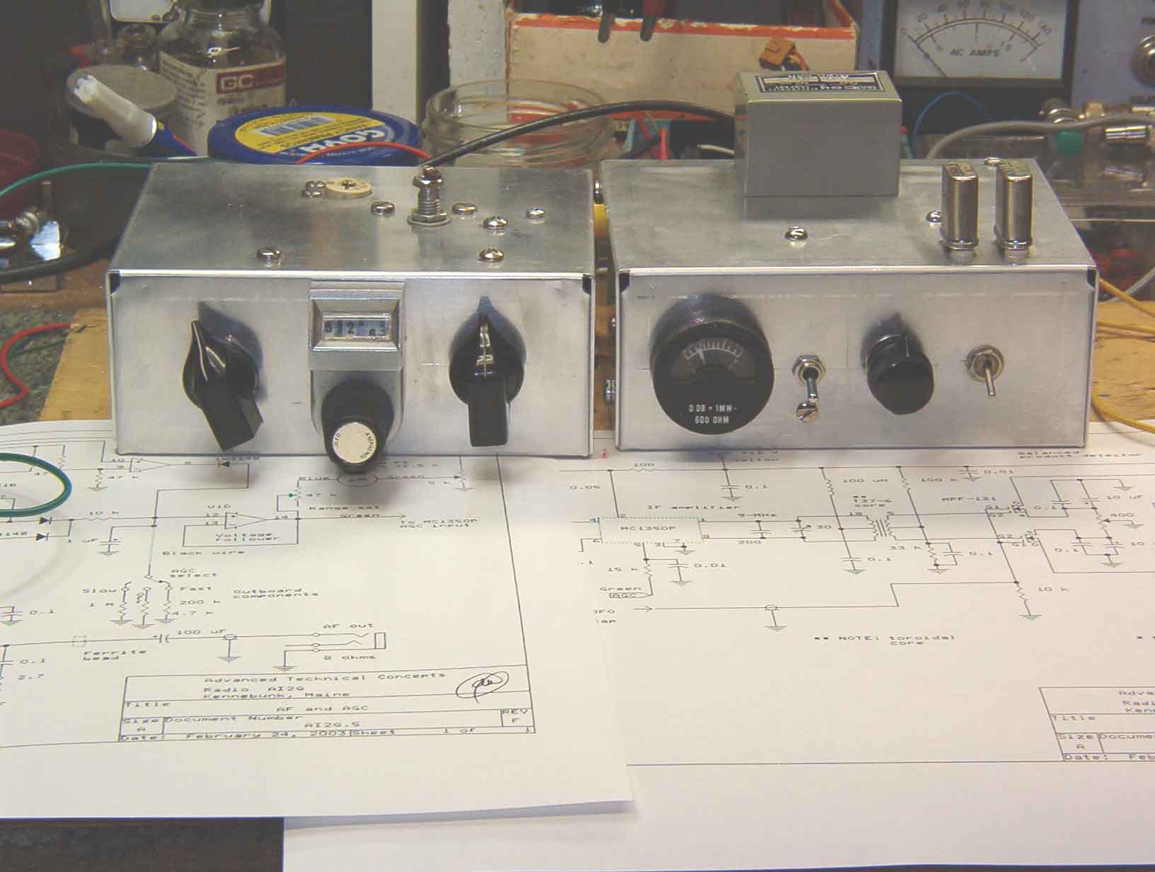
Click image for larger photo. The KISS project stemmed from a desire to build a simple selectable sideband SSB transceiver for one band. The goal was to achieve on-the-air performance that would be indistinguishable to a listener from that of any other transceiver heard on the band. Moreover, the rig would be simple enough to demonstrate that any Radio Amateur could duplicate it from junkbox parts and with a minimum of test equipment. It is far from state-of-the-art, but it reflects what can be done with junkbox parts. NOTE: If you're interested in a state-of-the-art high performance all-band transceiver, follow the links to the STAR project, above, and skip KISS. If you just want to get some ideas, read on. The design commenced with the rig's receiver section. The goal was performance that would make it stable and selective, with enough audio output power to drive a loudspeaker to normal room volume. A 9-MHz IF includes a steep-skirted crystal bandpass filter. The design would also have to include an AGC system that would permit listening to both strong and weak signals without having to make an AF gain control adjustment. It was decided to use a modular approach throughout the design and the KISS's construction. Individual modules, enclosed in small aluminum chasses, would be used, and circuit blocks would reside within these modules on appropriately partitioned sub-boards. Here's what the completed receiver section looks like. Click here for image. Click these tinted buttons for more circuit and construction details. The boxes show receiver circuits and modules, VFO, BFO, IF, SSB generator, TX mixer, driver and PA stages. All design goals were met. |
|||
| More KISS transceiver circuit details | Click
on pix for AF/IF amplifier views:
|
Transmitter speech-amp/balanced modulator schematic | Speech amplifier/microphone buffer stage | Speech amplifier/balanced modulator module details | SSB generator and pre-driver stages |
| Initial transmitter-mixer/pre-driver schematic. See updated broadband circuit diagrams in circuit descriptions, too! | Driver and PA stages. First QSO details! | AR |
 navigating


