| The VFO output board also
accommodates the receiver's mixer circuitry. Note that no
RF amplifier was used. The mixer is fed directly from the
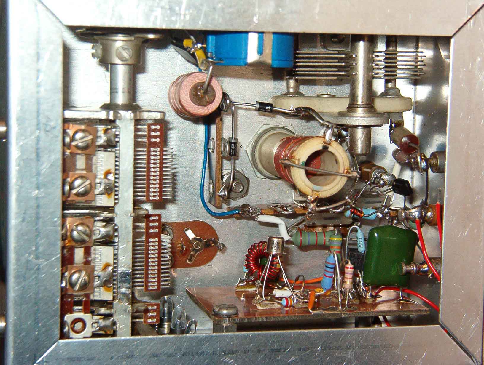
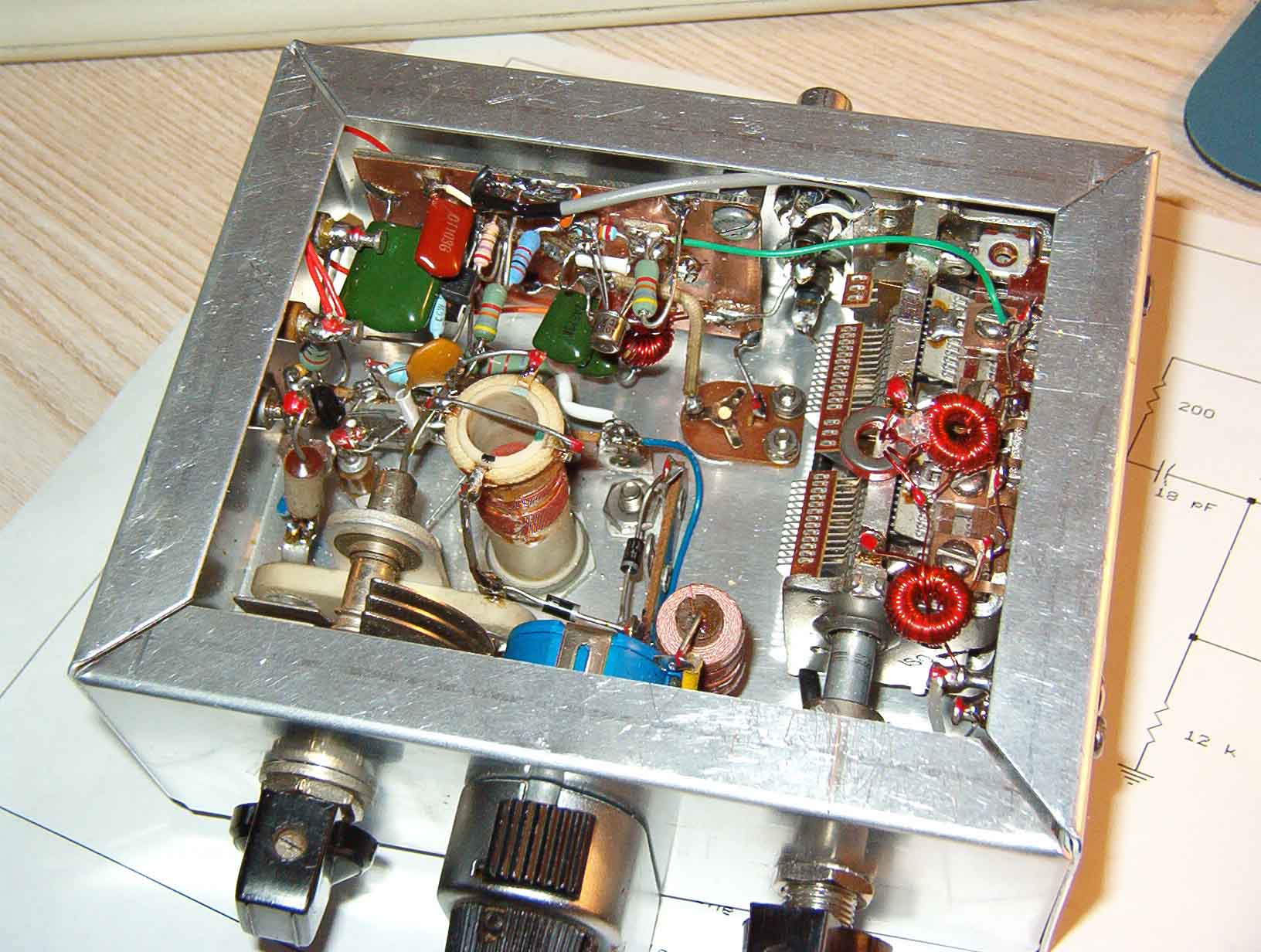
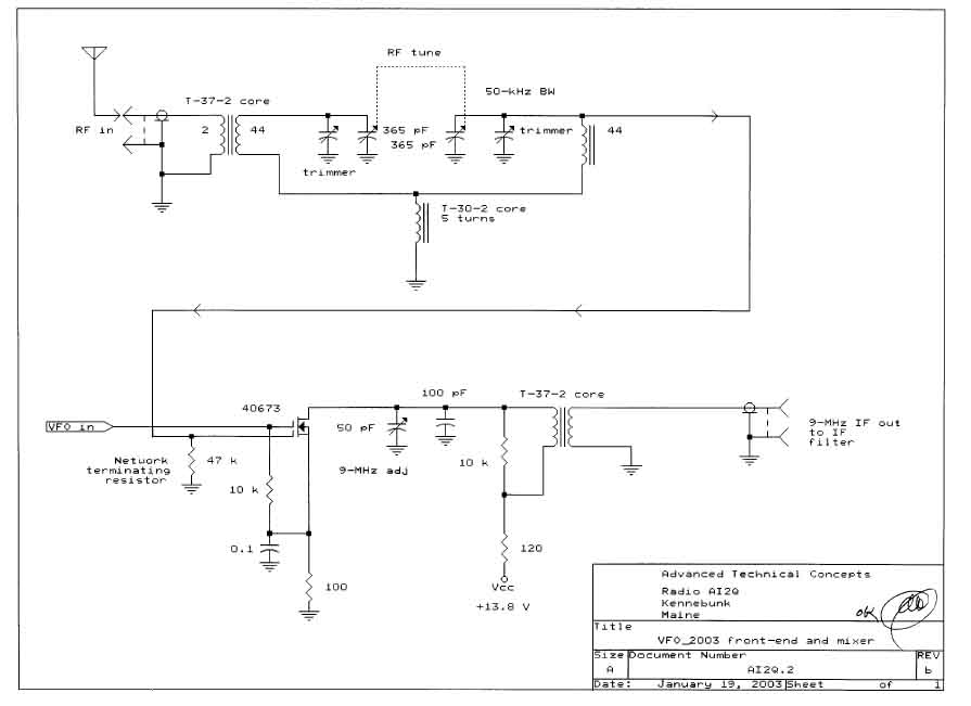
receiver's tuned pre-selector circuitry. On the 75-meter band, an RF amplifier would unnecessarily complicate the front-end, and also possibly result in degraded signal-handling capability. Atmospheric and band noise at 3.8 MHz makes an RF amplifier unnecessary. Click here for a schematic of the receiver section front-end and mixer circuitry. Here's what the VFO buffer/mixer board looks like (below, left) when fully populated.
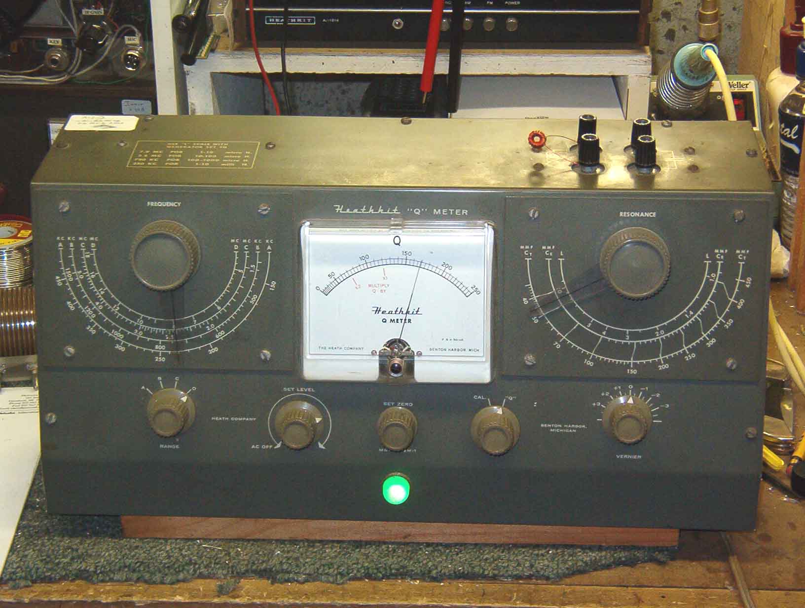
Click for a magnified photo that shows the details of the installed mixer circuitry, as well as the placement of the front-end tuning capacitor. The tuned circuit inductors aren't yet in place, nor is the 9-MHz mixer output wired. However, the 9-MHz variable tuning trimmer capacitor is in place. The second photo (above, right) shows the completed assembly, with all front-end wiring in place. Click here for a magnified view. A Heathkit Q-meter was used to match the toroidal coils to ensure front-end tracking. The mixer is based on a 40673 dual-gate MOSFET. This component isn't critical; other dual-gate MOSFETs, such as MPF-131s, can be substituted. At 3.8-MHz, lead dress and component placement isn't critical. |
||||
| Click to continue
to BFO circuit details. Use your browser's BACK button to return to the previous page. Click here to return to the home page. |