Because the buffer isn't temperature sensitive, and will not contribute to drift, it's acceptable to mount this block on a small circuit board.
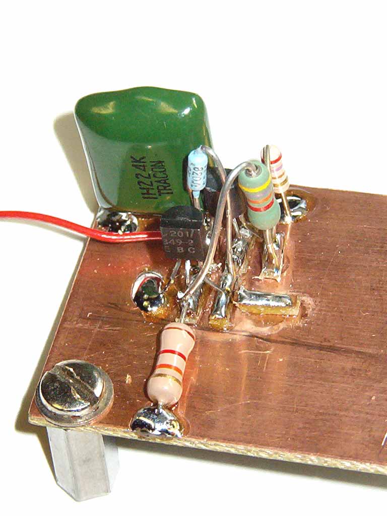
Assembled Manhattan-Style
The technique for assembling this board, and others in the KISS transceiver, is called "Manhattan construction." You can learn more about this assembly technique by visiting the K8IQY Web page.
Manhattan assembly is very fast, and while not necessarily the best looking method of constructing homebrew discrete-component circuitry, it works very well.
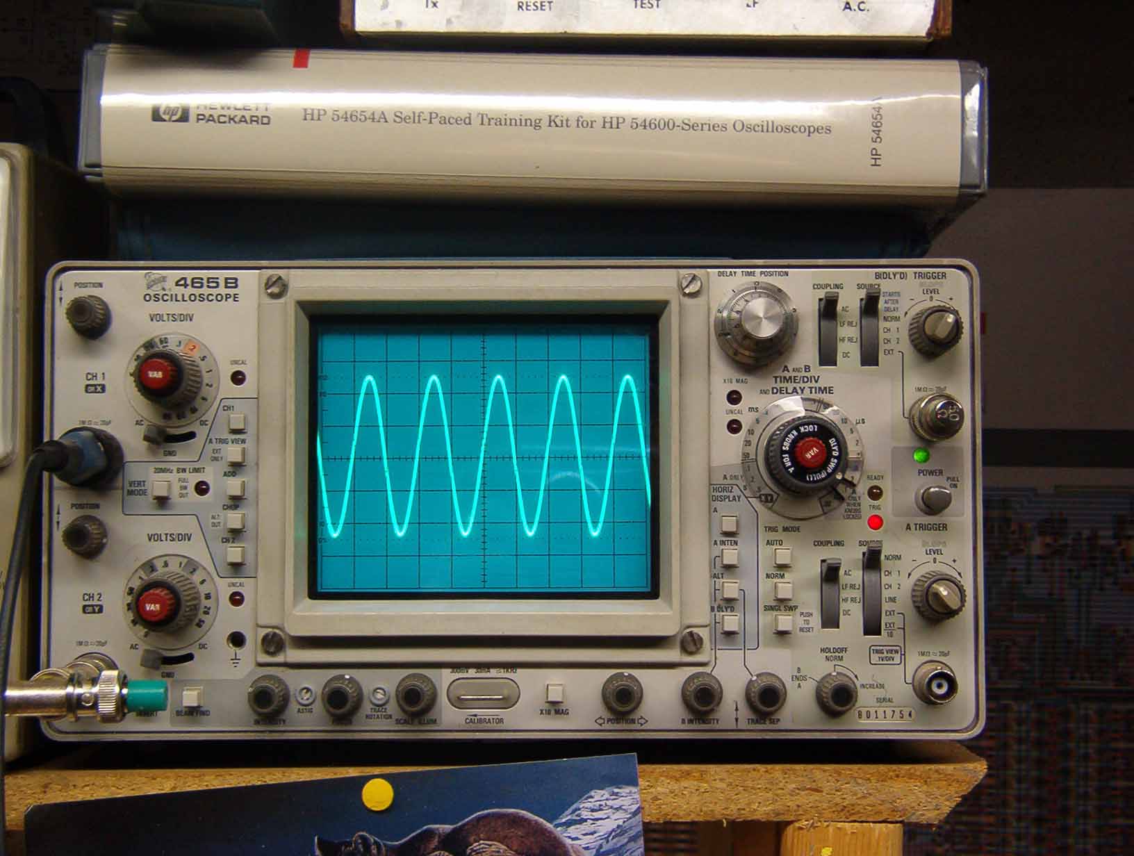
Here's what the unbuffered VFO output looks like on an oscilloscope. Nice sinewave, eh? Stable, too.
The buffer circuitry installed looks like this.
Or, click here to return to home page.